A specialized transceiver must turn a high-speed electrical stream into light, carry it through fiber, and recover the information with acceptable energy and error margin. The modulator performs the electrical-to-optical conversion and influences downstream power, loss, control, and signal budgets.
Its bandwidth, drive, loss, extinction, linearity, and stability shape the waveform delivered to the network. As module rates rise, the surrounding interfaces become less forgiving. Drivers consume more power, electrical paths lose more signal, optical engines contain more lanes, and thermal density increases.
A modulator that reduces one burden may enable a more suitable architecture, provided that its package and controls preserve the benefit across manufacturing variation and environmental operation. Architecture reviews quantify how a change in modulator voltage affects driver efficiency, cooling, and board area, connecting component improvements with measurable module economics.
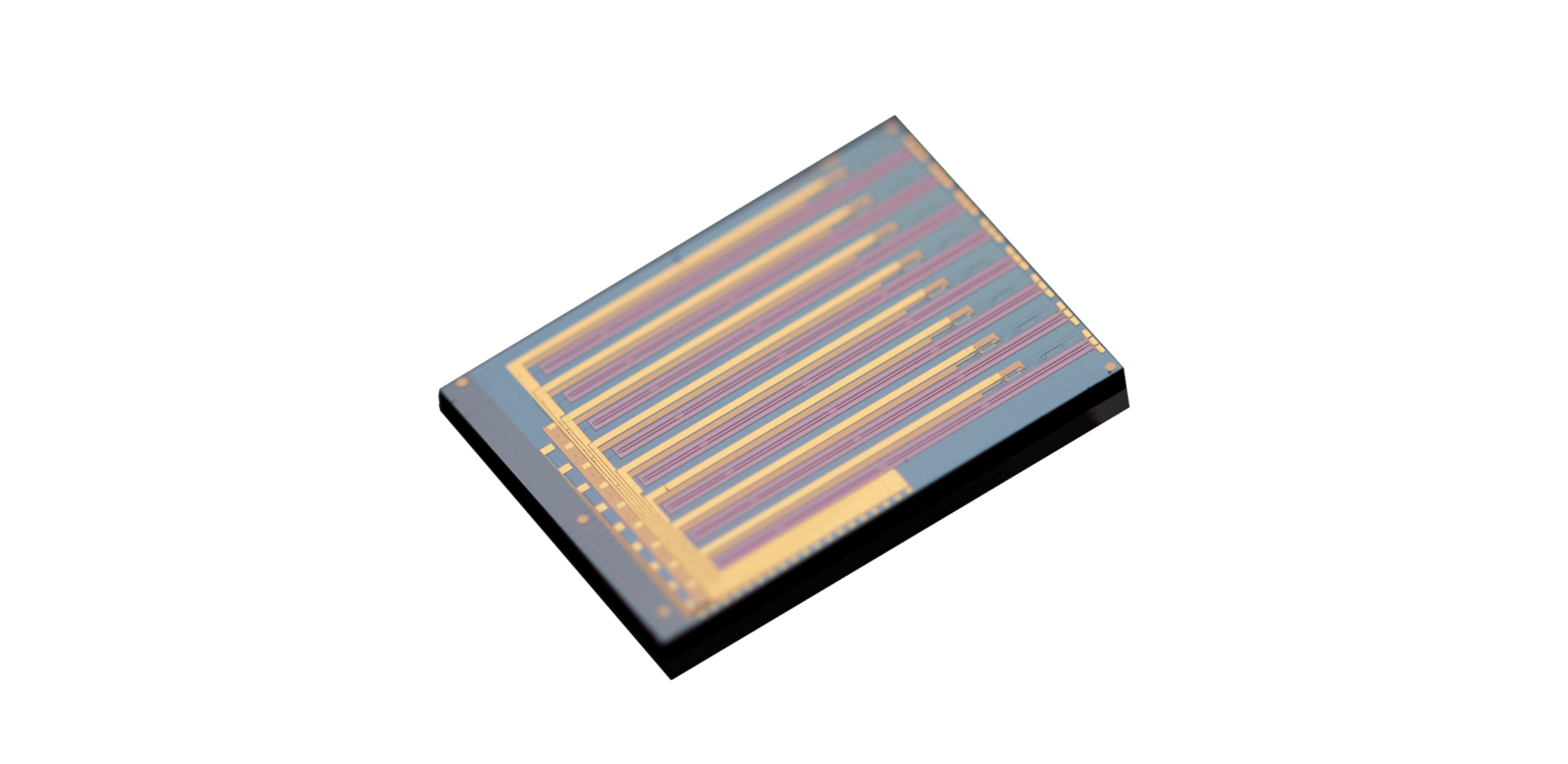
For specialized transceivers, TFLN Devices include high-speed intensity, phase, IQ, integrated-source, and comb functions. They use this range to show why modulation must be selected by link format and reach. The correct device provides the required optical operation while fitting the transceiver power, optical budget, footprint, test method, and supply model.
The Modulator Defines How Electrical Data Enters the Optical Link
In direct-detection transceivers, optical modulators create controlled intensity levels that the receiver converts back into electrical data. They define symbol rate, extinction, chirp tolerance, bandwidth, and linearity with the intended driver.
The modulator and detector are tested together because their combined response determines the eye opening and error margin available after the fiber path. TFLN devices can offer practical half-wave voltage at high bandwidth, potentially reducing driver swing. The system gain depends on package response and electrode matching.
They measure at the delivered connector and include cables and board launches. A low chip-level voltage is less useful if the electrical path requires additional gain or equalization to overcome transition loss. Insertion loss directly affects laser power and receiver margin.
They create an optical budget covering coupling, modulation, multiplexing, connectors, and fiber, then include aging and temperature. Extinction and waveform quality are considered at the same time. A device with lower loss but insufficient modulation depth may not improve the final link.
Different Transceiver Formats Require Different Modulation Functions
Coherent optical modulators perform amplitude and phase control, usually through nested interferometers and several bias points. This enables QPSK and QAM formats but adds balance, skew, and control requirements. They evaluate the complete constellation, error vector, and spectral behavior with the intended laser and DSP rather than judging the IQ package by bandwidth alone.
The TFLN device portfolio lists a 40 GHz IQ option with insertion loss below 6.5 dB and half-wave voltage below 3.5 V. Other products include 40 GHz phase and intensity functions and a 67/110 GHz intensity device below 4.5 dB loss and 3 V.
They match each specification set to the transceiver format instead of treating the portfolio as one performance ladder. An integrated low-RIN source can reduce external components in a 40 GHz intensity assembly and provides listed on-state output of 12 dBm.
This may simplify alignment and sourcing, yet it couples laser lifetime, wavelength, thermal behavior, and replacement strategy to the modulator package. They compare integration with a separate-source architecture over the full service model. They retain margin for connector contamination and laser aging, because a transceiver qualified at beginning-of-life conditions may create avoidable service failures.
System Qualification Must Preserve Performance Through Packaging and Control
Qualification of optical modulators begins with representative packages and several samples. They measure response, loss, extinction, bias, waveform quality, and temperature behavior, then repeat across lots. Reliability tests apply optical, RF, thermal, and mechanical stress appropriate to the module.
The goal is a controlled operating distribution, not confirmation that one sample meets a typical figure. TFLN devices also need production and field controls. They correlate wafer, packaged-device, and module tests; define bias and monitoring telemetry; and establish process-change rules. If a field unit degrades, traceable data should help distinguish the modulator, laser, connector, driver, or control loop.
Diagnosability reduces support cost and accelerates corrective action. Commercial selection includes capacity, package partnerships, calibration, failure-analysis response, and lifecycle continuity. A transceiver program may depend on the modulator for several generations.
They assess whether the supplier can support volume and maintain interface consistency, and whether replacement products can be qualified without redesigning the complete optical engine. Launch plans coordinate firmware, calibration files, incoming inspection, and spare inventory so that the new optical engine can be supported from initial customer deployment.
At the transmitter boundary, optical modulation is important because it determines how accurately and efficiently an electrical waveform becomes an optical signal. The component influences speed, laser demand, driver power, signal quality, packaging, controls, and test. Its value appears when those effects improve the complete transceiver rather than one isolated laboratory metric.
They select devices by starting with link architecture, then validating delivered packages with the intended electrical and optical interfaces. Multi-lot evidence, reliability work, manufacturing trials, and field diagnostics show whether the design can sustain its margin.
This process keeps rising module rates connected to repeatable production and manageable operation. The modulator’s contribution appears in driver power, optical budget, controls, package variation, and aging across the complete transceiver. Comparing Liobate functions in that system gives the release team module-level evidence and a practical view of service needs.
